Communication Protocols – I2C
A blog on Communication Protocols – I2C
I2C Protocol – Inter-Integrated Circuit
I2C stands for Inter Integrated Circuit, and is one of the most important communication protocols. It was developed by Philips Semiconductor, which is now known as NXP Semiconductors. Let’s get to know how it works.
Overview
- Full form: Inter-Integrated Circuit
- Type: Bidirectional, serial protocol
- Nature: Synchronous communication (due to the clock line)
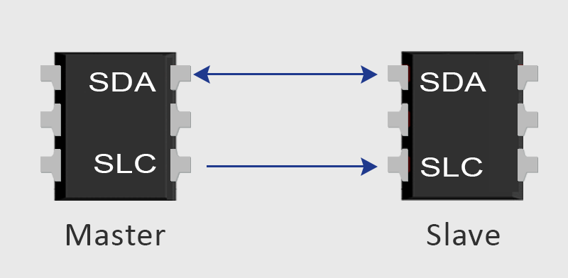
- Wires: 2-wire protocol
- SCL – Serial Clock Line
- SDA – Serial Data Line
- Addressing: Supports 7-bit and 10-bit addressing
- Configuration: Master-slave (can support multiple masters and multiple slaves)
- Number of devices are limited by bus capacitance
- Example:
- Master: Controller
- Slave: Memory
Speed Modes
- Standard mode: ≤ 100 Kbit/s
- Fast mode: ≤ 400 Kbit/s
- Fast mode plus: ≤ 1 Mbit/s
- High speed: ≤ 3.4 Mbit/s
- Ultra-fast mode: ≤ 5 Mbit/s
Open-Drain Configuration
The output stage of the devices connected to the I2C bus must have an open-drain configuration.
An open drain (or open collector) is the setup where:
- An nMOS transistor has its:
- Source connected to ground
- Base connected to the input
- Drain left open
This leads to two conditions:
- When transistor is active → The value at drain (‘D’) is 0 (pulled down)
- When transistor is inactive → The value is floating
This configuration is used with a pull-up resistor, so that the line defaults to HIGH when idle, and can be pulled LOW to indicate activity.
Hence, in the I2C bus, SDA can be pulled LOW from its HIGH (default) state to indicate the start of a transaction.
How the Transfer Works?
Step 1: Start and Stop Conditions
- Start Condition:
- SDA:
1 → 0while SCL is1→ Start the transaction
- SDA:
- Stop Condition:
- SDA:
0 → 1while SCL is1→ Stop the transaction
- SDA:
Note:
Data on SDA should never change when SCL is 1, except during start or stop conditions.
A master can only occupy the bus if it is IDLE. If the bus is BUSY, it must wait until it’s free.
Step 2: Data Transfer
- After the start condition, 1-bit transfer occurs per clock cycle
- Data transfer format: Byte-wise (1 byte = 8 bits)
- Each byte is followed by an ACK/NACK bit
- Number of bytes is unrestricted
Clock Stretching
If the target (slave) is not ready to send/receive, it holds SCL LOW (pauses the clock).
The data transfer resumes once SCL is released.
Address Transfer
- Every device on the I2C bus has a unique address
- After START, the master sends the address + R/W bit
- Target device sends ACK if address matches
Data Transfer
WRITE (R/W bit = 0)
- Master sends bytes of data
- Receiver/slave sends ACK after each byte
READ (R/W bit = 1)
- Slave takes control of the bus and sends data to master
- Master sends ACK after each byte
Step 3: Stop Condition
- SDA is pulled HIGH while SCL is HIGH → Indicates STOP
- The bus is released and becomes IDLE again
Additional Important Points
ACK/NACK Bit
- After each byte, the receiver pulls SDA LOW during the 9th clock cycle → ACK
- If SDA remains HIGH during this clock pulse → NACK (no acknowledgement)
- Master then stops or re-initiates the transfer
Bus Arbitration
If multiple masters try to access the bus simultaneously:
- Arbitration is done bit-by-bit
- The master that sends a ‘0’ while others send ‘1’ wins
Example:
- Transfer seen from MSB first
- Master 3 sends ‘1’ while others send ‘0’ → Master 3 loses
- Master 1 later sends ‘1’ while Master 2 sends ‘0’ → Master 1 loses
- Master 2 wins
Addressing Modes
7-Bit Addressing
- Address byte = 7-bit address + 1-bit R/W flag = 8 bits
10-Bit Addressing
- After START, 2 bytes are sent:
- First Byte:
11110XX(R/W)- Devices matching this pattern ACK
- All matched devices read the second byte
- Second Byte:
XXXXXXXX- Target device acknowledges again
If First Byte is
11111XX(R/W)→ Reserved for future I2C enhancements
Cons of I2C
- Frame overhead due to ACK/NACK and addressing → Slower effective data rate
- Half-duplex communication
- Increased hardware complexity with multiple masters/slaves